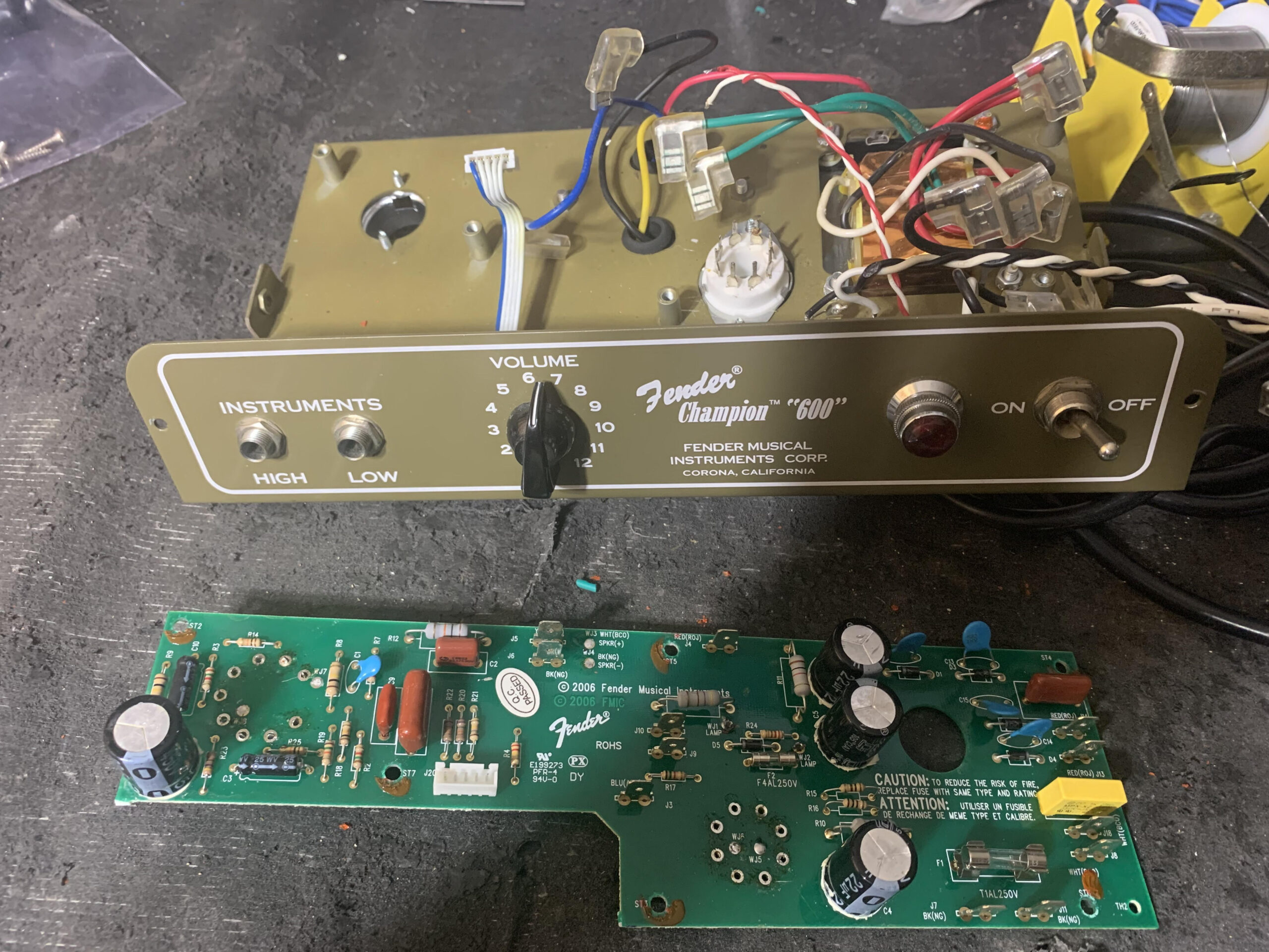
Champ 600 upgrade to point to point wiring
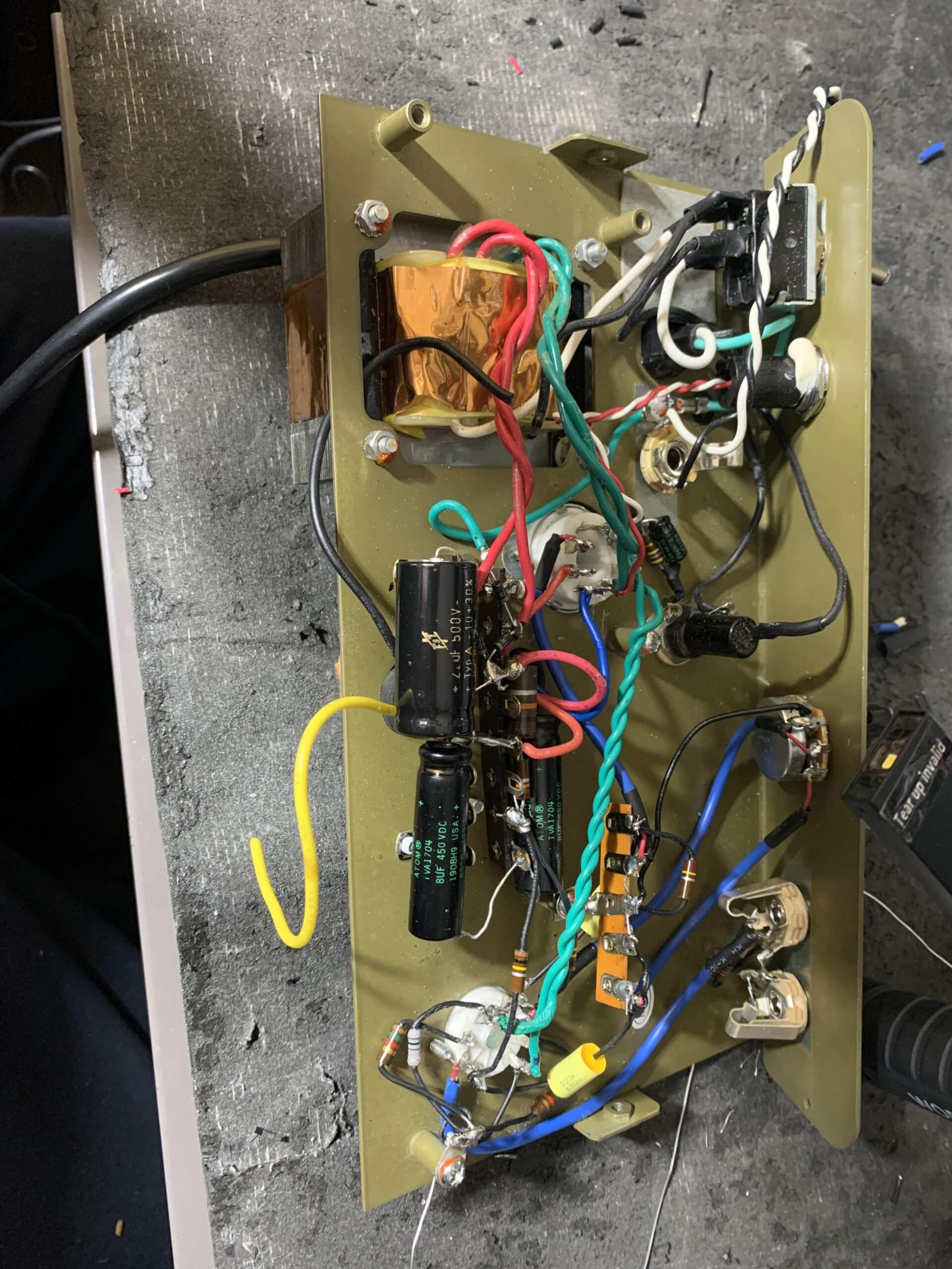
Here at TubeAmpRepairShop.com Tube Amp Repair Shop we have completed two Fender Champ 600 projects removing the circuit board and wiring the amplifiers point to point.
We added a high quality feature which is a variable feedback loop allowing for hi clarity or more breakup depending where you set the knob.
If you would like to upgrade your Fender Champ 600 to a point to point amp with an amazing sound call Eric 818 645-1075.
The price for the upgrade is $250.00.
Here is feedback from the customer
“Every once in a while you run across an out of the ordinary product or person that impresses you more than any other.
Eric and his Tube Amplifier repair and design business are just that.
I have received two tube amplifiers that he converted from a pc based to a point-to-point design.
The quality and performance of both of of these amps are the best that I have ever seen.
In addition, I have had the pleasure of watching Eric work on his bench with the skill and expertise of a craftsman who loves what he does. These qualities are rare today and something to be admired.

Reference fender 5F1 Champ
Shopping list
1 Switch craft single throw double pole toggle
2 Fuse holder
3 9 pin sockets
4 Terminal strips (2) 8 holes each
5 diodes 4 in4007 1,000v 1amp
6 10 k resistor from first capacitor node to
Steps
1 disassemble from cabinet
2 unsolder sockets
3 disconnect all wires volume pot and jacks
4 lift board
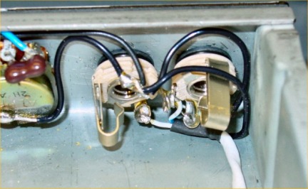
5 green heaters
Red hi voltage
6 black hot
White return
7 output transformer note wire to b+
8 need full wave rectifier
9 drill fuse holder
10 check black white wire iec plug jack not backwards
11 mount 9 pin socket to chassis
12 put rivet in terminal strips
13 add diodes all pointing forward
14 Twist red wires to rectifier
15 test with multi meter
16 test voltages
17 ground wire from negative rectifier terminal
18 add first cap 22 uf 500v positive end to positive end full wave rectifier.
19 connect filtered end of cap to red wire output transformer.
20 Add 10k resistor to first node of power supply
21 other end of resistor is second node. There will be 3 exits or connections
22 At 2nd node exit 1. a wire to screen of the 6V6. This is pin 4 on the socet.
23 Exit 2. A 22k resistor to the 3rd node.
Exit 3 a 10 uf electrolytic filter cap
Tools
Rivet gun
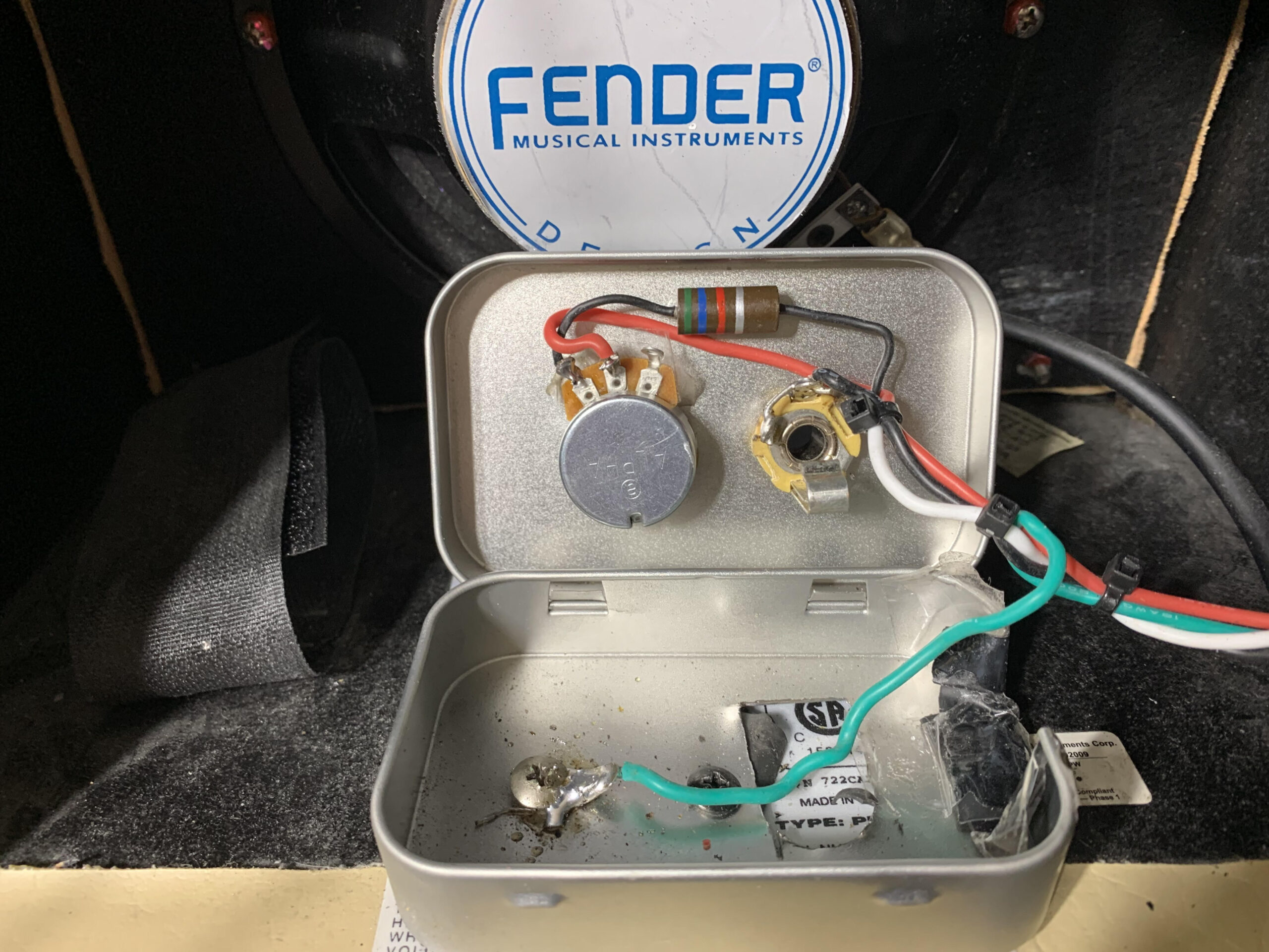
Mound red box two screws
Drill hole right side for wires
Drill two holes in box top for
potentiometer on left
Jack on right
Feed back loop
From 12ax7 socket pin 8
To junction of white speaker wire the tip
Jack is near feedback potentiometer
Run short wire from pot to jack
Run one longer wire to pin 8 preamp socket